
matter.jsで曲がりくねった棒状のBodyを作ろうとすると思った以上に大変である。
Bodies.fromVertices()やSvg.pathToVertices()で座標点を指定して作ると、凹面が含まれる形状の場合は凸包形(凹面が埋められる)に変換されてしまうためdecomp.jsを使う必要があり、あまり複雑な形状だと思い通りに機能してくれないことが多い。さらに、これらの関数ではドーナツ形のように空洞を含む形状はサポートされていない。
そこで、もっと単純な条件の入力だけで等幅の曲がりくねった棒状のBodyを生成できる関数を作成してみた。
棒の生成の考え方
関数的には棒の骨格となる中心線の座標データと棒の幅だけを引数として渡す。
やはりBodies.fromVertices()を使うが、棒全体の座標を与えて一気に作るのではなく、棒の節点(屈折部分)と節点の間に四角形を1つずつ生成してそれらを最後にくっつけて1本の棒にするという方針になる。
中心線の各節点から腕(棒の幅と曲がりの角度に応じて長さが変わる)を左右に伸ばして、棒の1部品となる四角形の頂点の座標を決める。
なお、ここで言う棒の左側・右側とは、中心線の進行方向を見た時の左側・右側という意味で使っている。
中心線の各線分の傾きの計算
中心線のn、n+1番目の節点を$S_n(x_n, y_n)$, $S_{n+1}(x_{n+1}, y_{n+1})$とした時、線分$S_nS_{n+1}$がx軸の正の向きとなす角$\theta_n$を計算する。
線分$S_nS_{n+1}$の傾きを$m$とすると、両節点のx, y座標の値から$\theta_n$は下記のように求められる。
$$ m = \frac{y_{n+1} - y_n}{x_{n+1} - x_n} = \tan \theta_n $$
$$ \theta_n = \tan^{-1}m $$
これと同等の計算は、javascriptのMath.atan2() 関数を利用すればいい。Math.atan2() は、原点 (0, 0) から任意の1点 (x, y) までの半直線とx軸の正の向きのなす角をラジアン単位で返す。原点以外の2点間で計算したい場合は、2点のx, y座標の差分をそれぞれ引数に指定すればいい。引数はy, xの順で渡す必要がある。
なお、数学的には角の向きは反時計回りを正とするが、matter.jsではy軸が下向きなので角の向きは時計回りが正となる点に注意する必要がある。

節点から左右に伸びる腕の長さの計算

節点$S_n$, $S_{n+1}$間に四角形(図の黄色い部分)を作る時、
四角形の両端の辺(図の$P_1P_2$, $P_3P_4$)が中心線の屈折角の二等分線となるようにしてやると、棒の幅に基づいて自然な感じで屈折部を作ることができる。
$\angle S_{n-1}S_nS_{n+1}$は線分$P_1P_2$で等分されるので、まずは右側の角$\alpha_n$を求める。
$$ \alpha_n = \frac{180^{\circ} - (\theta_n + \theta_{n-1})}{2} = 90^{\circ} - \frac{\theta_n + \theta_{n-1}}{2} $$ であるが、$\theta_n$と$\theta_{n-1}$の回転方向を考慮すると図の場合は$\theta_n \gt 0$, $\theta_{n-1} \lt 0$なので、
$$
90^{\circ} - \frac{\theta_n - \theta_{n-1}}{2}
$$
になる。屈折のパターンに応じて$\theta_{n-1}$, $\theta_n$の値が変わってくるが、いずれの場合もこの式で$\alpha_n$を計算することができる。
次に、節点から左右に伸ばす腕の長さ、つまり線分$S_nP_1$または$S_nP_2$の長さ$l_n$を求める。棒の右側の$P_1$から反対側へ下ろした垂線の足を$H_n$とし、線分$P_1H_n$と$P_1P_2$のなす角を$\beta_n$とすると、図形的な関係から$\beta_n$は次のように求められる。
$$ \beta_n = 90^{\circ} - \alpha_n = \frac{\theta_n - \theta_{n-1}}{2} $$
線分$P_1H_n$の長さ、つまり棒の幅を$t$とすると、これはあらかじめ引数で与えられるもので既知であるから、$l_n$は下記のように求められる。
$$ l_n = \frac{1}{2} \left| \frac{t}{\cos \beta_n} \right| $$
四角形を構成する4頂点の座標の計算

四角形の形状と位置を決定するために、4頂点$P_1$, $P_2$, $P_3$, $P_4$の座標を求める。色々やり方はあると思うが、ここでは座標点の回転移動を利用して求めることにする。なお、四角形の両端の辺について、線分$P_1P_2$を始点側の辺、線分$P_3P_4$を終点側の辺と呼ぶことにする。
まずは始点側の$P_1$, $P_2$の座標を計算する。 回転移動の対象とする点を$Q_s(x_s, y_s)$とする。$Q_s$は線分$S_nS_{n+1}$上に点$S_n$からの距離が$l_n$となるよう取れば計算しやすい。この時$Q_s$の座標は下記の計算で求められる。
$$ \begin{cases} x_s = x_n + l_n \cos \theta_n\\ y_s = y_n + l_n \sin \theta_n \end{cases} $$
後は、節点$S_n$周りに$Q_s$を$+\alpha_n$回転して右側の$P_1$の座標が求まり、$P_1$を180°回転して$P_2$が求まる。
終点側の$P_3$,$P_4$の座標の計算も同様に計算する。 回転移動の対象とする点を$Q_e(x_e, y_e)$として、線分$S_nS_{n+1}$上に点$S_{n+1}$からの距離が$l_{n+1}$となるように取る。この時$Q_e$の座標は下記の計算で求められる。
$$ \begin{cases} x_e = x_{n+1} - l_{n+1} \cos \theta_n\\ y_e = y_{n+1} - l_{n+1} \sin \theta_n \end{cases} $$
この後はやはり節点$S_{n+1}$周りに$Q_s$を回転して$P_3$,$ P_4$を求めるのだが、四角形を構成する都合上$P_1$→$P_2$→$P_3$→$P_4$の順で決定していかなければならないので先に左側の$P_3$を計算する。 $P_3$の座標は$Q_e$を節点$S_{n+1}$周りに$Q_s$を(180° − $\alpha_{n+1}$)回転し、$P_4$は$P_3$を180°回転すれば求まる。
座標の回転移動について
ここで、行列を用いた座標の回転移動について少しまとめておく。
一般に、座標の回転移動を表す行列は下記のように表す。
$$ \begin{pmatrix} \cos \theta & -\sin \theta \\ \sin \theta & \cos \theta \\ \end{pmatrix} $$
ただし、この行列は原点周りの回転を表したものであり、原点以外の任意の点周りの回転を行う場合は平行移動も組み合わせる必要がある。
画像処理などでは、点の平行移動:Translationと線形変換(回転:Rotation、拡大縮小:Scaling、せん断:Skew)をまとめてアフィン変換と呼び、3x3の行列で表すのが一般的である。せん断については今回は省くが、平行移動量$T_x$, $T_y$、回転角度$\theta$、拡大率$S_x$, $S_y$を表す行列は下記のように表される。
$$ \begin{pmatrix} S_x\cos \theta & -\sin \theta & T_x \\ \sin \theta & S_y\cos \theta & T_y \\ 0 & 0 & 1 \end{pmatrix} $$
特に今回は平行移動と回転移動しか考慮しないので$S_x$, $S_y$は1である。
任意の点$A(x_a, y_a)$の周りに点$B(x, y)$を$\theta$回転して点$B’(x’, y’)$に移す、つまり$\overrightarrow{AB}$を$\overrightarrow{AB’}$に変換することを考えるとき、次のように3段階の変換に分けて適用する必要がある。
① $\overrightarrow{AB}$の始点$A$を原点と重なる点$A_0$まで平行移動する(点$B$の移動先を点$B_0$とする)
$$ \begin{pmatrix} 1 & 0 & -x_a \\ 0 & 1 & -y_a \\ 0 & 0 & 1 \end{pmatrix} $$
② $\overrightarrow{A_0B_0}$を$\theta$回転する(点$B_0$の移動先を点$B_0'$とする)
$$ \begin{pmatrix} \cos \theta & -\sin \theta & 0 \\ \sin \theta & \cos \theta & 0 \\ 0 & 0 & 1 \end{pmatrix} $$
③$\overrightarrow{A_0B_0’}$の始点$A_0$を元の点$A$に戻るように平行移動する
$$ \begin{pmatrix} 1 & 0 & x_a \\ 0 & 1 & y_a \\ 0 & 0 & 1 \end{pmatrix} $$

これらの変換行列を点Bに適用(変換行列はオリジナルの座標に順次左側から掛け合わせていく)して点B’に変換することを式で表すと、
$$ \begin{pmatrix} x'\\ y'\\ 1 \end{pmatrix}= \begin{pmatrix} 1 & 0 & x_a \\ 0 & 1 & y_a \\ 0 & 0 & 1 \end{pmatrix} \begin{pmatrix} \cos \theta & -\sin \theta & 0 \\ \sin \theta & \cos \theta & 0 \\ 0 & 0 & 1 \end{pmatrix} \begin{pmatrix} 1 & 0 & -x_a \\ 0 & 1 & -y_a \\ 0 & 0 & 1 \end{pmatrix} \begin{pmatrix} x\\ y \\ 1 \end{pmatrix} $$
これを展開して整理すると、
$$ \begin{cases} x' = x\cos \theta - y\sin \theta - x_a\cos \theta + y_a\sin \theta + x_a \\ y' = x\sin \theta + y\cos \theta - x_a\sin \theta - y_a\cos \theta + y_a \end{cases} $$
四角形の中心座標の計算
4頂点$P_1$, $P_2$, $P_3$, $P_4$の配列をBodies.fromVertices()に渡せば棒の部品となる四角形を生成できる。しかし、4頂点の正確な中心座標を計算してfromVertices()の引数に指定しないと、本来生成したい位置からずれた所に四角形が生成されてしまいきれいな棒状にならない場合がある。
そこで、4頂点の中心座標を求めるために、一旦4頂点の座標値を元にMatter.Verticesオブジェクトを作る。このVerticesオブジェクトをVertices.centre()の引数として渡せば一発で中心座標を返してくれる。
ただし、Vertices.centre()で中心を計算するためには$P_1$→$P_2$→$P_3$→$P_4$と辿った時にぐるっと一周する位置関係でなければならず、クロスする位置関係になっていると正しく中心を計算することができない。

このようなクロスする位置関係になってしまうのは下記の2パターンである。
$$ \begin{cases} \frac{\theta_n - \theta_{n-1}}{2} \lt -90^{\circ} \rightarrow \alpha_n \lt 0^{\circ} \cdots (1)\\ \frac{\theta_n - \theta_{n-1}}{2} \gt 90^{\circ} \rightarrow \alpha_n \gt 180^{\circ} \cdots (2) \end{cases} $$
(1)(2)になるのは、下の図のように隣り合う角$\theta_n, \theta_{n-1}$が共に鈍角かつ異符号の時である。

(1)の場合は$\alpha_n$に180°を足し、(2)の場合は$\alpha_n$から180°を引くという補正を行えばクロスすることはなくなる。
ソースコード
ここまでの考え方に示した内容をコードに書き起こした。
/**
 * 中心線に沿った棒状のBodyを生成する
 */
function createMeandering(sections, thickness, shouldClose = false, options ={}) {
  const parts = [];
  const sectionAngles = [];

  // パスを閉じる場合、先頭の節点を末尾に追加する
  if (shouldClose) {
    sections.push(sections[0]);
  }

  for (let j = 0; j < sections.length; j++) {
    if (j !== sections.length - 1) {
      // 2頂点の線分とx軸のなす角度を計算する
      sectionAngles.push(Math.atan2(sections[j + 1].y - sections[j].y, sections[j + 1].x - sections[j].x));
    }
  }

  if (shouldClose) {
    const beginningAngle = sectionAngles[0];
    const endAngle = sectionAngles[sectionAngles.length - 1];
    sectionAngles.unshift(endAngle);
    sectionAngles.push(beginningAngle);
  } else {
    sectionAngles.unshift(sectionAngles[0]);
    sectionAngles.push(sectionAngles[sectionAngles.length - 1]);
  }

  for (let j = 0; j < sections.length; j++) {
    if (j !== sections.length - 1) {
      const vertices = [];

      // 始点側の2頂点を生成する
      const armAngle1 = (sectionAngles[j + 1] - sectionAngles[j]) / 2;
      const armLength1 = Math.abs(thickness / (2 * Math.cos(armAngle1)));
      const startRadius = { x: sections[j].x + armLength1 * Math.cos(sectionAngles[j + 1]), y: sections[j].y + armLength1 * Math.sin(sectionAngles[j + 1]) };
      // 始点側の回転角度を計算する
      const rotAngle1 = calcRotAngle(-armAngle1);
      // 始点側の動径ベクトルを回転して2頂点の座標を計算する
      vertices.push(rotate(sections[j], startRadius, rotAngle1));
      vertices.push(rotate(sections[j], vertices[0], Math.PI));

      // 終点側の2頂点を生成する
      const armAngle2 = (sectionAngles[j + 2] - sectionAngles[j + 1]) / 2;
      const armLength2 = Math.abs(thickness / (2 * Math.cos(armAngle2)));
      const endRadius = { x: sections[j + 1].x - armLength2 * Math.cos(sectionAngles[j + 1]), y: sections[j + 1].y - armLength2 * Math.sin(sectionAngles[j + 1]) };
      // 終点側の回転角度を計算する
      const rotAngle2 = calcRotAngle(armAngle2);
      // 終点側の動径ベクトルを回転して2頂点の座標を計算する
      vertices.push(rotate(sections[j + 1], endRadius, rotAngle2));
      vertices.push(rotate(sections[j + 1], vertices[2], Math.PI));

      // 4頂点で作られるVerticesオブジェクトの中心座標を求める
      const tetragon = Vertices.create(vertices, Matter.Body);
      const center = Vertices.centre(tetragon);
      // 四角形を生成してpartsに追加する
      parts.push(Bodies.fromVertices(center.x, center.y, vertices, options));
    }
  }

  // 結合前のパーツの配列を返却する
  return parts;
}

/**
 * 任意の点の周りに座標点を回転する
 */
function rotate(origin, target, rotAngle) {
  // 回転移動対象の点を、原点周りに平行移動 → 原点周りの移動 → 元の任意点周りに戻す
  const x = target.x * Math.cos(rotAngle) - target.y * Math.sin(rotAngle) + origin.x - origin.x * Math.cos(rotAngle) + origin.y * Math.sin(rotAngle);
  const y = target.x * Math.sin(rotAngle) + target.y * Math.cos(rotAngle) + origin.y - origin.x * Math.sin(rotAngle) - origin.y * Math.cos(rotAngle);

  return { x, y };
}

/**
 * 回転角度を計算する
 */
function calcRotAngle(armAngle) {
  let rotAngle = Math.PI / 2 + armAngle;
  // 回転角度が0°より小、180°より大になる場合の補正
  if (armAngle > Math.PI / 2) {
    rotAngle -= Math.PI;
  } else if (armAngle < -Math.PI / 2) {
    rotAngle += Math.PI;
  }

  return rotAngle;
}
| 中心線の座標データの配列 | [object] |
| 棒の幅 | number |
| パスを閉じるフラグ | boolean |
| Matter.Bodyのオプション | object |
メインの処理を行う関数。
指定が必須な中心線の座標データの配列と棒の幅の他に、パスを閉じるフラグとしてtrueを指定することで棒の始点と終点を自動的に結んで閉じたような形状を作れるようにした。
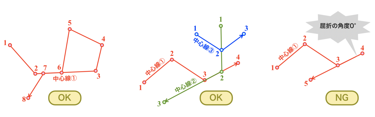
なお、中心線の屈折角が0°になる区間を含む場合はうまく生成できないので注意が必要。
なお、最終的に1本の棒状とする場合はcreateMeandering()から返るBodyの配列を別途結合してやる必要がある。個々の四角形を結合してから返すようにすると、そのBodyに対してさらに別のBodyを結合した時にやはり凸包形に変換されてしまうのでこのような返却の形にした。
| 回転の中心点の座標 | object |
| 回転対象の点の座標 | object |
| 回転角度(ラジアン) | number |
任意の点の周りに座標点を回転する関数。
| 節点から伸びる腕の角度(ラジアン) | number |
長方形の4頂点を計算するために中心線上の点を回転する角度を計算する関数。
回転角度が0°より小、180°より大になる場合の補正もここで行う。
使用例
新潟県
const mainland = [
  { x: 466.9, y: 59.2 }, { x: 445.5, y: 105.8 }, { x: 439.7, y: 159.7 }, { x: 397.1, y: 206.4 }, { x: 324.3, y: 245.8 },
  { x: 283.6, y: 327.7 }, { x: 225.5, y: 392 }, { x: 181.2, y: 428 }, { x: 59.7, y: 477.1 }, { x: 77.8, y: 494.1 },
  { x: 87.8, y: 534.1 }, { x: 118.8, y: 498.8 }, { x: 142.1, y: 503 }, { x: 146, y: 522.7 }, { x: 199.3, y: 513.4 },
  { x: 225.5, y: 471.9 }, { x: 257.4, y: 466.7 }, { x: 267.1, y: 497.8 }, { x: 283.6, y: 510.3 }, { x: 286.5, y: 544.5 },
  { x: 316.6, y: 536.2 }, { x: 335, y: 517.5 }, { x: 349.6, y: 481.2 }, { x: 372.8, y: 460.5 }, { x: 392.2, y: 484.3 },
  { x: 405.8, y: 483.3 }, { x: 400, y: 422.1 }, { x: 390.3, y: 408.6 }, { x: 398.4, y: 356.5 }, { x: 435.8, y: 349.6 },
  { x: 476.6, y: 335 }, { x: 468.8, y: 301.8 }, { x: 507.6, y: 253.1 }, { x: 486.2, y: 232.3 }, { x: 499.8, y: 157.7 },
  { x: 527.9, y: 147.3 }, { x: 538.6, y: 127.6 }, { x: 506.6, y: 106.9 }, { x: 501.8, y: 71.6 }
];

const sado = [
  { x: 260.3, y: 184 }, { x: 235.9, y: 236.9 }, { x: 185.9, y: 259.2 }, { x: 207.9, y: 213.3 }, { x: 198.4, y: 205.7 },
  { x: 188.3, y: 214 }, { x: 192.5, y: 185.9 }, { x: 237.7, y: 122.9 }, { x: 255, y: 119.7 }, { x: 241.9, y: 159.8 },
  { x: 234.7, y: 187.2 }
];

const options = {
  render: {
    fillStyle: '#6b8e23'
  }
}

const mainlandParts = createMeandering(mainland, 10, true, options);
const sadoParts = createMeandering(sado, 10, true, options);
const niigata = Body.create({ parts: [...mainlandParts, ...sadoParts], isStatic: false });

Composite.add(engine.world, niigata);

// 床
Composite.add(engine.world, Bodies.rectangle(400, 585, 800, 30, { isStatic: true }));

図形の入れ子
// 正多角形の節点座標を計算する関数
function polygonSections(center, sides, radius) {
  const sections = [
    { x: center.x, y: center.y - radius }
  ];
  const rotAngle = 2 * Math.PI / sides;
  for (let i = 0; i < sides - 1; i++) {
    sections.push(rotate(center, sections[i], rotAngle));
  }

  return sections;
}

// 正二十角形
const icosagonSections = polygonSections({ x: 300, y: 200 }, 20, 200);
// 正六角形
const hexagonSections = polygonSections({ x: 300, y: 200 }, 6, 150);
// 星形
const starSections = [
  { x: 300, y: 100 },{ x: 358.78, y: 280.9 },{ x: 204.89, y: 169.1 },{ x: 395.11, y: 169.1 },{ x: 241.22, y: 280.9 }
];
// 床
const floorSections = [
  { x: 0, y: 400 },{ x: 100, y: 440 },{ x: 200, y: 470 },{ x: 300, y: 490 },{ x: 400, y: 500 },
  { x: 500, y: 490 },{ x: 600, y: 470 },{ x: 700, y: 440 },{ x: 800, y: 400 },
];

const options = {
  inertia: 1e7,
  density: 1,
}

const icosagon = createMeandering(icosagonSections, 30, true, { ...options, render: { fillStyle: '#ffd700' }});
const hexagon = createMeandering(hexagonSections, 15, true, { ...options, render: { fillStyle: '#0000ff' } });
const star = createMeandering(starSections, 10, true, { ...options, render: { fillStyle: '#ff0000' } });
const floor = createMeandering(floorSections, 30, false, { ...options, render: { fillStyle: '#4d4d4d' } });

Composite.add(engine.world, Body.create({ parts: icosagon }));
Composite.add(engine.world, Body.create({ parts: hexagon }));
Composite.add(engine.world, Body.create({ parts: star }));
Composite.add(engine.world, Body.create({ parts: floor, isStatic: true }));
